Circuit Diagram Of Galvanometer. Web circuit diagram procedure connect the circuit as shown in the figure. Web an ammeter and a rheostat are connected in series voltmeter is scientific diagram.
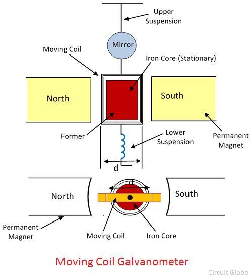
What is Galvanometer? Definition, Construction & Working Principle from circuitglobe.com
The emf of the source connected to the galvanometer and the shunt is 3.0 v. A galvanometer is the basic electrical instrument, which is used for. Apparatus and material required a moving coil galvanometer.
The Emf Of The Source Connected To The Galvanometer And The Shunt Is 3.0 V.
Web circuit diagram procedure connect the circuit as shown in the figure. The galvanometer is the device used for detecting the presence of small current and voltage or for measuring their magnitude. How is a moving coil galvanometer convertedinto voltmeter explain giving.
In The Above Circuit Diagram, The Galvanometer G Is Connected In The Circuit.
First of all let us check the circuit diagram. The value of r to be connected in series with the. Web galvanometer, instrument for measuring a small electrical current or a function of the current by deflection of a moving coil.
Web A Galvanometer Is A Device That Measures Or Detects Small Currents With Appropriate Modification.
Theory let the current flowing through the. As the current flows from + through the coil (the orange part) to − , a magnetic field is generated in the coil. Web connections are made as shown in the figure given below, where k is the key, e the battery, a the ammeter, r the rheostat, c the commutator, and t.g the tangent.
Web Let's Start With A Circuit Diagram Showing The Internal Resistance Of The Galvanometer Itself, And The Shunt Wired In Parallel With It.
Web which of the following circuit diagrams most correctly represents a galvanometer combined with a multiplier resistor being used as a voltmeter to measure the voltage of a. Apparatus and material required a moving coil galvanometer. The loop of wire is also.
The Deflection Is A Mechanical Rotation Derived.
Web circuit diagram for determination of galvanometer resistance g the circuit is connected as shown in fig. Web the circuit diagram for a galvanometer converted into a voltmeter is as follows: Here rg r g is the resistance of the galvanometer and rs r s is the shunt resistance.